Four-Jaw Self-Centering Gripper Mechanism Explained: The Tire Gripper Design


Gripping a tire sounds simple until you actually try to automate it: the part is round, heavy, and needs to be held firmly from four sides at once—evenly, every time, regardless of small size variation between tires. A single pneumatic cylinder driving four independent grippers with separate linkages would be complex, heavy, and hard to keep synchronized.
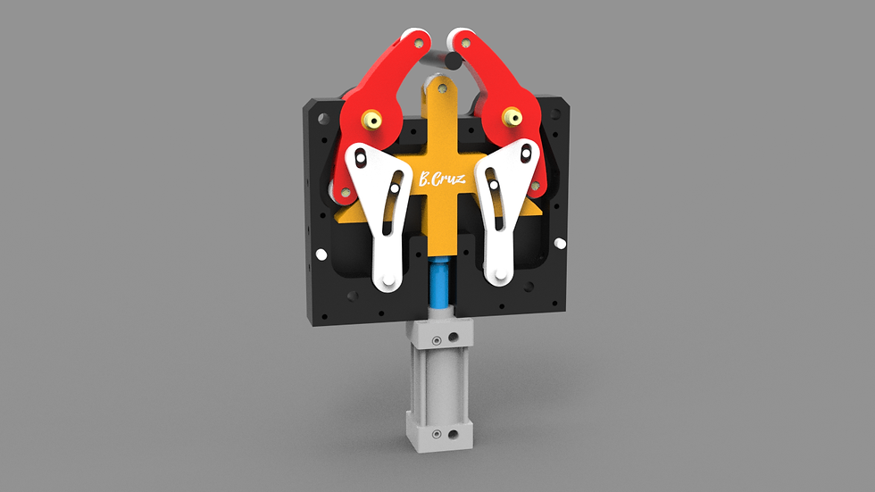
This mechanism solves that with a single piston stroke driving all four jaws simultaneously and evenly, through three mechanisms working in sequence: a rotating cylinder mechanism, a tangent slider mechanism, and a balanced lever jaw system. Below is how each stage works, why it self-centers automatically, and what to consider if you want to model or build your own version.
What Is a Four-Jaw Self-Centering Gripper Mechanism?
A self-centering gripper is a chucking mechanism where multiple jaws move inward or outward together, by equal amounts, from a single actuator input—unlike an independent chuck, where each jaw is adjusted separately.
This tire-gripper design uses three stages:
Rotating cylinder mechanism: converts the pneumatic piston’s linear stroke into rotation.
Tangent slider mechanism: converts rotation into synchronized radial motion of four sliders.
Balanced lever jaw system: converts slider motion into jaw clamping, with springs balancing the load.

Download the CAD File
Grab the CAD files (it’s free)
Stage 1: The Rotating Cylinder Mechanism
The pneumatic cylinder doesn’t push the jaws directly. Instead, its piston drives a swivel nut threaded onto a screw shaft. As the piston extends/retracts, the threaded engagement converts linear motion into rotation of a central disk.
A screw joint between the piston and nut also sets the adjustable operating limit—effectively calibrating how far the disk (and downstream motion) travels for a given stroke.
Stage 2: The Tangent Slider Mechanism
The rotating disk has curved runways that engage four sliders constrained to move radially in straight guide slots. As the disk rotates, the runway geometry forces each slider to move inward/outward—converting rotation into synchronized radial slider motion.
Because all four sliders are driven by the same disk, they stay matched automatically. This is the same core principle used in spiral scroll plates of self-centering machine-shop chucks.
Stage 3: The Balanced Lever Jaw System
Each slider drives a jaw through a lever action, translating radial travel into clamping motion. Four identical springs keep the system mechanically balanced, helping the jaws settle into a centered, evenly loaded grip—important for tires, which are compliant and vary slightly.
How the Full Mechanism Works (Step by Step)
Pneumatic input: cylinder extends/retracts.
Rotation conversion: screw + swivel nut converts stroke into disk rotation.
Synchronized radial motion: disk runways drive all four sliders equally.
Jaw closure: sliders transmit motion through levers to the jaws.
Spring balancing: springs allow small adjustments so load shares evenly.
Adjustable limit: screw joint sets the operating range for different diameters.
Why Self-Centering Beats Independent Jaws Here
Independent four-jaw designs offer flexibility for irregular parts, but require manual adjustment or multiple actuators. For repetitive tire handling—round parts with small variation—a self-centering mechanism is simpler, lighter, and easier to control: one actuator, one rotating disk, and geometry synchronizes everything.
Real-World Applications
Tire handling and changing equipment
Machine-shop self-centering chucks (same principle)
Robotic end-of-arm tooling for round parts
Automated palletizing/material handling of drums, spools, cylinders
Designing This Mechanism in CAD
Derive runway curves from the required slider displacement vs. rotation angle (don’t “sketch by eye”).
Constrain sliders in single-axis slots first, then add disk engagement.
Parameterize lever pivots and spring anchors for quick iteration.
Simulate the full open-close cycle to check binding and spring travel.
Designing for 3D Printing
Separate high-wear interfaces (disk runways + slider guides) and finish them for smooth motion.
Use real compression springs (matched rates matter).
Test the swivel nut + screw joint in isolation (backlash here amplifies downstream).
Common Problems and Troubleshooting
One jaw closes first: uneven spring rates or slider binding.
Disk binds mid-rotation: runway curve not derived from the displacement function.
Backlash before motion: thread clearance in the screw-and-nut stage.
Frequently Asked Questions
How does one pneumatic cylinder drive four jaws evenly? Linear stroke → rotation (screw + swivel nut) → four sliders driven by one disk → synchronized jaw motion.
What’s the purpose of the four balancing springs? They equalize load and accommodate small misalignment/variation so all jaws share contact.
Is this the same as a lathe chuck? Same core principle (one rotating element driving multiple jaws), adapted for pneumatic input and compliant parts.
What adjusts the operating range for different tire sizes? The screw joint between piston and swivel nut, which limits disk travel.
Related Mechanisms
Explore more in 3D Mechanisms and Mechanical Movements.


Comments