Synchronized Double Rack and Pinion Mechanism: One Push, Perfect Counter-Rotation

Updated: Aug 4

How do automated robotic grippers, transit doors, and industrial clamps open and close in perfect, mirrored symmetry — at the exact same instant, every single cycle — without two motors, two sensors, or any electronic timing at all? The mechanical answer is a synchronized double rack and pinion mechanism: a single linear stroke driving two gears into perfectly matched, counter-rotating motion.
This article breaks down how the mechanism works, why the synchronization is mechanically guaranteed rather than just well-tuned, where it shows up in real machines, and what to watch for if you model it yourself in CAD.
What Is a Synchronized Double Rack and Pinion Mechanism?
This mechanism converts a single reciprocating linear input into synchronized counter-rotary output, using three core parts:
The linear actuator: A pneumatic or hydraulic cylinder that pushes a central rod out in a straight line — a simple, common source of linear force with no rotation of its own.
The double-sided rack: A straight gear bar with teeth cut into both its top and bottom edges, mounted to the end of the cylinder's rod so it travels linearly with the piston.
The pinion pair: Two separate gears — one meshing with the rack's top row of teeth, the other with the bottom row — positioned on opposite sides of the rack so they engage independently.
The key detail that makes this configuration different from a typical rack-and-pinion gripper: it's one rack meshing with two pinions, not two racks meshing with one pinion. That distinction is what turns a single linear push directly into two independent rotary outputs, rather than into two linear outputs.

How It Works
Linear input. The cylinder extends, pushing the double-sided rack straight out along its axis.
Top-face engagement. As the rack moves, its top row of teeth pushes against one pinion, forcing it to rotate in one direction — counter-clockwise, for example.
Bottom-face engagement, simultaneously. At the very same instant, the rack's bottom row of teeth pushes the second pinion in the opposite rotational sense — clockwise, in this case — because it's meshing with teeth on the opposite face of the same moving rack.
Mechanically locked timing. Because both pinions are driven by teeth cut into the same physical rack, moving at the same linear speed, neither pinion can rotate faster or slower than the geometry dictates. There's no possibility of one side lagging behind the other — the synchronization isn't tuned or calibrated, it's a direct consequence of both gears meshing with a single shared rack.
Output. Whatever is mounted to each pinion's shaft — gripper jaws, door paddles, clamp arms — rotates outward or inward together, in mirrored symmetry, for the full length of the cylinder's stroke.
Why the Synchronization Is Guaranteed, Not Just Accurate
It's worth being precise about why this mechanism is genuinely different from "two motors running the same program." With two independent actuators, synchronization depends on matched timing, matched load, and (usually) some form of electronic control keeping both sides in step — any friction difference or control lag between the two sides shows up as a mismatch.
Here, both pinions are geometrically constrained by the same rack. The top and bottom tooth rows share the exact same linear position at every instant, because they're cut into the same physical part. There is no failure mode where one pinion "gets ahead" of the other without the rack itself deforming — which, for a properly sized rack, isn't a realistic failure mode at all. This is what makes the design attractive anywhere symmetric motion matters more than raw speed or force: the accuracy comes from geometry, not from tuning.
Download the CAD File
Grab the CAD files (it’s free)
How This Differs From Similar-Looking Mechanisms
The name "double rack and pinion" gets applied to more than one distinct layout, and it's worth being clear about which one this is:
Mechanism | Configuration | Motion conversion |
Synchronized double rack and pinion (this mechanism) | One double-sided rack, two separate pinions | Reciprocating linear input → synchronized counter-rotary output |
Classic two-rack, single-pinion gripper (common in pneumatic parallel grippers) | One central pinion, two racks on opposite sides | Rotary input → two mirrored linear outputs (used for parallel-jaw grippers) |
Sector pinion and double rack | A partial-tooth pinion alternating engagement with two stacked racks | Oscillating rotary input → reciprocating linear output |
All three use the phrase "double rack" or "double pinion" in different senses, and it's easy to conflate them when researching — but they solve different motion-conversion problems and aren't interchangeable in a design.
Real-World Applications
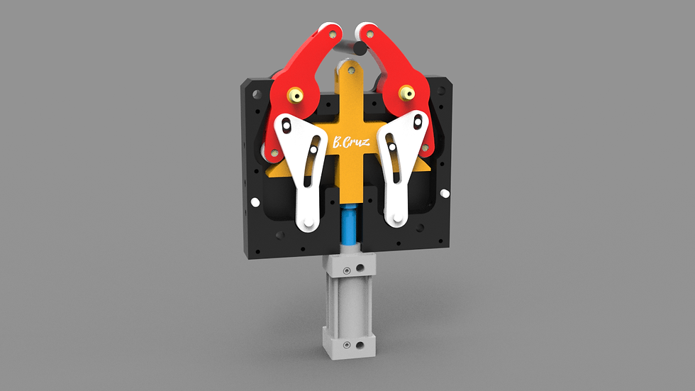
Pneumatic robotic grippers — opening and closing two gripper arms in perfect mirrored symmetry from a single cylinder.
Automated transit and elevator doors — driving two door panels to open or close at exactly the same rate without separate motors on each panel.
Self-centering vices and clamping fixtures — ensuring both clamping faces move inward by equal amounts so the workpiece stays centered.
Steering linkages — some steering mechanisms use a comparable rack-driven dual-output arrangement to keep linked components synchronized.
Industrial clamping fixtures — any fixture needing two rotating clamp arms to close symmetrically around a part.
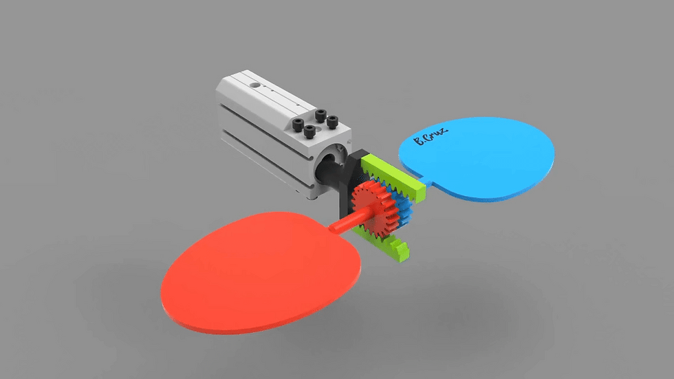
Controllable-pitch ship propellers — in some designs, a linear actuator drives a central rack along the propeller shaft, meshing with a small spur gear on the base of each blade to rotate every blade's pitch angle simultaneously. It's one of several actuation methods used in controllable-pitch propellers (others include pin-slot and crank-and-ring hydraulic arrangements), but where it's used, it relies on the same rack-driving-multiple-pinions principle covered in this article — extended from two pinions to several, arranged radially around the hub instead of on opposite faces of a single rack.
Designing This Mechanism in CAD
Setting up the mechanical mates for a double rack and pinion assembly is genuinely one of the trickier parts of this design, mainly because of pitch diameter and clearance:
Match both pinions' pitch diameter and module to the rack's tooth spacing exactly. Since both pinions mesh with the same rack, any mismatch between the two pinions' geometry — even a small one — throws off the mirrored symmetry that's the whole point of the mechanism.
Check for gear clipping between the two pinions before finalizing spacing. Because the pinions sit close together on opposite faces of the rack, it's easy to size the rack's thickness too thin and end up with the two pinions' addendum circles overlapping — always verify clearance in a static check before running a motion simulation.
Constrain the rack to pure linear travel first, then add the two pinion meshes — debugging the linear guide and both gear meshes simultaneously makes it hard to isolate which constraint is causing binding if something goes wrong.
Run the motion simulation through the full stroke length, not just the neutral position, to confirm neither pinion runs out of engaged rack teeth before the cylinder reaches full extension.
Common Design Mistakes
Sizing the rack too thin for the pinion spacing, causing the two pinions' teeth to physically clip each other rather than clear correctly on opposite faces of the rack.
Using mismatched module or pressure angle between the two pinions, which breaks the mirrored symmetry even though each individual mesh might look fine in isolation.
Under-sizing the rack length for the required rotation angle — the rack needs enough total tooth length to rotate both pinions through their full intended range without running off the end.
Confusing this layout with a two-rack, single-pinion gripper during early design — they solve opposite motion-conversion problems, and starting with the wrong one means rebuilding the whole kinematic layout later.
Frequently Asked Questions
How does one linear push create two opposite rotations? A single rack has teeth cut into both its top and bottom edges. As it moves linearly, the top teeth mesh with one pinion and the bottom teeth mesh with a second pinion on the opposite side — because the teeth are cut in mirrored orientation relative to each pinion, the two pinions are forced to rotate in opposite directions from the same linear motion.
Why is this more reliable than using two separate motors? Because both pinions are driven by teeth on the same physical rack, their relative timing is fixed by geometry rather than by control tuning — there's no synchronization error to correct for, since one pinion mechanically cannot move independently of the other.
Is this the same mechanism used in pneumatic parallel grippers? Not exactly — many pneumatic parallel grippers use the reverse layout (one central pinion between two racks, converting rotary input into two mirrored linear outputs). This mechanism instead uses one rack between two pinions, converting linear input into two mirrored rotary outputs.
What's the biggest design risk in CAD? Gear clipping between the two pinions if the rack isn't sized thick enough for the pinion spacing, and mismatched pitch diameter or module between the two pinions, which quietly breaks the mirrored symmetry the mechanism depends on.
Related Mechanisms
Explore more in 3D Mechanisms and Mechanical Movements.


Comments