Timing Screw Mechanism Explained: How Factories Perfectly Space Thousands of Cans a Minute


Cans and bottles arrive at a packaging line completely jammed together, riding shoulder-to-shoulder on a fast-moving conveyor. By the time they reach the labeler or filler a few feet downstream, they're perfectly, evenly spaced — one container per pocket, no crowding, no gaps. No servo motors picking up individual containers, no vision system tracking positions. Just one spinning shaft with a cleverly shaped groove cut into it.
That's a timing screw (also called a feed screw or metering screw), and the secret is hiding in plain sight in the shape of the screw itself: the thread pitch isn't constant. This article breaks down exactly how that variable pitch forces containers apart, what it takes to model the geometry correctly in CAD, and where this mechanism shows up across packaging and manufacturing.
What Is a Timing Screw?
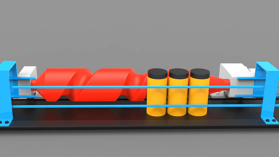
A timing screw is a rotating shaft with a deep helical groove — the same basic idea as a machine screw thread, but built at a much larger scale and shaped specifically to capture and space discrete objects rather than fasten two parts together. It sits alongside a conveyor, spinning continuously, with containers riding on the belt and dropping into the groove as they pass.
The one detail that makes it work: the spacing between the threads (the pitch) is not uniform along the screw's length. Near the infeed end, the threads sit close together to gently capture containers that are still bunched up. Moving down the screw's length, the pitch gradually widens — and because each container is trapped inside its own thread pocket, that widening groove physically forces the containers apart as the screw rotates.

Download the CAD File
Grab the CAD files (it’s free)
How It Works, Step by Step
Backlog at the infeed. Containers arrive on the conveyor completely back-to-back, with no gap between them.
Capture. As the screw rotates, the first, tightly-spaced threads at the infeed end gently pick off the leading container, trapping it in the pocket between two adjacent thread flights.
Progressive widening. As that container travels down the length of the rotating screw, it moves into sections where the thread pitch is progressively larger — because it's confined between two flights of the helix, the container has no choice but to follow the widening gap.
Forced spacing. By the time the container reaches the discharge end, it has been mechanically pushed into the exact spacing the pitch geometry defines — not by pushing it faster, but by controlling exactly how far it can travel relative to the screw's rotation.
Release. At the discharge end, the container exits the timing screw already at the correct pitch, ready to be handed off to a starwheel, filler, or labeling station running in sync with it.
The Detail Most People Get Backwards: Pull, Not Push
It's tempting to assume the screw actively pushes containers apart faster and faster. In properly designed systems, it's closer to the opposite: the conveyor belt underneath is set to run somewhat faster than the screw's effective feed rate, so the belt is what's actually moving the containers forward — the timing screw's job is to hold each container back on pitch, not to accelerate it. Every container rides against the leading edge of its thread pocket, driven by the faster-moving belt beneath it, while the widening groove controls exactly how far ahead each one is allowed to get. This is also why timing screw systems are typically set up with the conveyor running faster than the screw, rather than matched to it — if the screw tried to push containers forward on its own, the loose fit within each pocket would introduce wobble and inconsistent spacing instead of precise, repeatable positioning.
Timing Screw vs. Starwheel vs. Metering Belt
Method | How it spaces containers | Best suited for |
Timing screw (feed screw) | Variable-pitch helical groove holds containers back on pitch as a faster conveyor moves them forward | High-speed lines needing precise, positive spacing control; easy changeover by swapping screws for different container sizes |
Starwheel | Rotating wheel with pockets sized to the container, typically fed by a timing screw upstream | Transferring containers into rotary fillers, cappers, or labelers at a fixed indexed spacing |
Metering belt | A second conveyor belt running at a different speed to open up gaps between containers | Simpler, lower-cost spacing where precise, positive container control isn't critical |
Timing screws sit at the more precise, more positively-controlled end of this comparison — the tradeoff is that each screw is generally shaped for a specific container size and shape, so a size changeover often means physically swapping the screw rather than just adjusting a setting.

Real-World Applications
Bottling and canning lines — spacing containers evenly before filling or capping.
Automated labeling machines — ensuring each container arrives at the labeling head with consistent spacing and timing.
Capping equipment — feeding containers into capping heads at a controlled, synchronized rate.
Pharmaceutical packaging — precise spacing for vials and bottles moving into filling or inspection stations.
Starwheel infeed systems — timing screws are commonly used as the stage immediately before a rotary starwheel, handing containers off at exactly the pocket spacing the starwheel needs.
Modeling a Variable-Pitch Timing Screw in CAD
This is a genuinely advanced surfacing challenge, and it's worth approaching deliberately rather than trying to sketch the profile freehand:
Define the pitch as a function of position along the axis, not as a fixed value. Before starting the helical sweep, decide on the pitch progression you need — for example, tight pitch for the first several flights, transitioning smoothly to a wider, constant pitch by the discharge end — and treat that relationship as a driving curve for the sweep rather than eyeballing the spacing.
Use a variable-pitch helix or guide-curve sweep feature, rather than a standard constant-pitch helix tool. Most major CAD packages support defining a helix with pitch that varies along a guide curve or table of values — this is the feature to reach for instead of manually stacking multiple constant-pitch sections.
Model the thread profile to match your container's shape, not a generic V-thread. Real timing screws use custom flight profiles shaped to cradle the specific bottle or can geometry — a simple triangular thread section works for a first pass, but production designs shape the groove to the container's actual silhouette.
Check for self-interference at the tightest pitch section. The infeed end, where the pitch is smallest, is where the helical flights are most likely to overlap or interfere with each other if the thread depth and pitch aren't sized together correctly — verify this section specifically before committing to the full-length model.
Simulate a container moving through the full length, not just a static cross-section — the entire point of the geometry is what happens as an object travels along the changing pitch, so a motion study (even a simplified one, treating the container as a simple cylinder) is the real test of whether the profile behaves as intended.
Designing for 3D Printing
Print the screw axis-vertical, if your printer allows it, so the helical flights are supported by the layers below rather than requiring extensive support material along a long horizontal groove.
Check flight thickness against your printer's minimum wall guidelines, especially near the tight-pitch infeed section — thin, closely-spaced flights are the section most likely to come out weak or warped on an FDM print.
Test container capture on a short printed section first, rather than committing to a full-length print — verifying the pocket geometry actually captures and releases your target object correctly on a shorter test piece saves significant print time if adjustments are needed.
Common Problems and Troubleshooting
Containers wobble or arrive inconsistently spaced: Often a conveyor-to-screw speed mismatch — if the belt isn't running consistently faster than the screw's feed rate, containers won't stay pressed against the leading edge of their thread pocket the way the design assumes.
Containers jam at the infeed: Usually the initial pitch is too tight for the container's actual diameter, or the lead-in flight geometry doesn't smoothly capture an object arriving at conveyor speed.
Excessive wear at the discharge end: Can result from relative sliding motion between the container and the screw surface, particularly in high-speed lines or where the pitch changes more aggressively than the container's inertia can comfortably follow.
Frequently Asked Questions
Why does the timing screw's thread pitch change along its length? Because each container is trapped between two adjacent thread flights, a widening pitch physically increases the distance between the leading edges of consecutive pockets — spacing the containers apart as they travel from the tightly-packed infeed end to the evenly-spaced discharge end.
Does the timing screw push containers, or does the conveyor? In properly set up systems, the conveyor belt does the actual forward driving, typically running somewhat faster than the screw — the screw's role is to hold each container back on pitch against the leading edge of its pocket, giving much more consistent, repeatable spacing than trying to push containers with the screw directly.
What's the difference between a timing screw and a starwheel? A timing screw uses a continuously rotating helical groove to space containers along a conveyor; a starwheel is a rotating disc with fixed pockets that typically receives containers already spaced by an upstream timing screw and carries them through a fixed indexed rotation for filling, capping, or labeling.
Why is modeling the variable pitch difficult in CAD? Because the helix's pitch has to be defined as a function of position along the axis rather than as a single constant value, which requires a variable-pitch sweep feature and careful checking for self-interference at the tightest-pitch section, rather than a standard constant-pitch helix tool.
Related Mechanisms
Explore more in 3D Mechanisms and Mechanical Movements.


Comments