Four-Bar Linkage Explained: How It Works, Types, Grashof's Law, and Interactive Simulator

Updated: Aug 12

A four-bar linkage is the simplest closed-loop mechanism capable of producing continuous, controlled motion from a single rotary input. It's made of four rigid links connected end-to-end by four pin (revolute) joints, with one link fixed to the frame. Turn one link and the closed loop forces the other three into a precise, repeatable motion — a rocking arc, a full rotation, or a complex curve traced in space, depending entirely on the ratio of the link lengths.
It's arguably the single most-used mechanism in mechanical engineering. Windshield wipers, folding chairs, oil pumpjacks, bicycle rear suspensions, robotic grippers, and Watt's original steam engine linkage all reduce to some version of this same four-link idea.
To make all of this concrete, this guide comes with a free interactive four-bar linkage simulator you can use directly in your browser — no download, no login — so you can see everything explained below happen in real time on your own link lengths.
Try the Interactive Four-Bar Linkage Simulator
Adjust the ground, crank, coupler, and follower lengths and watch the mechanism update instantly — including its live classification as Crank-Rocker, Double-Crank, Triple-Rocker, Parallelogram, or Anti-Parallelogram, its Grashof condition, the current transmission angle, and angular velocity.
What you can do with it:
Drag the crank directly with your mouse to control rotation manually, step by step.
Hit Play for continuous automatic rotation at an adjustable RPM.
Watch the coupler curve trace live as the mechanism moves — the exact path any point on the floating coupler link follows through a full cycle.
Export the diagram as a PNG to save or share a specific configuration.
Copy all current values with one click — link lengths, Grashof classification, transmission angle, and angular velocity — to drop straight into your own notes or CAD parameters.
It's the fastest way to build real intuition for Grashof's condition: instead of just checking the inequality on paper, you can drag a slider past the threshold and watch a Crank-Rocker turn into a Triple-Rocker in real time.
What Is a Four-Bar Linkage?
A four-bar linkage consists of exactly four rigid links joined in a closed loop by four revolute (pin) joints:
The ground link (frame): Fixed in place; the other three links move relative to it.
The crank (driver): The input link, connected to the ground link, that receives rotation from a motor or manual input.
The coupler (floating link): Connected to both the crank and the follower, but not to the ground. Every point on the coupler traces its own unique path — the coupler curve — as the mechanism moves.
The follower (rocker/output): Connected to the ground link on the opposite side from the crank; it delivers the output motion, either oscillating back and forth or rotating fully.
Because it's a closed loop with exactly four one-degree-of-freedom pin joints, the whole assembly has a single degree of freedom — meaning one input (turning the crank) fully and predictably determines the position of every other link. That's the entire appeal of the mechanism: total motion control from a single rotary actuator, with no electronics and no timing to manage. Try setting the crank rotating in the simulator above and watch how deterministic the coupler and follower motion really is.
How a Four-Bar Linkage Works
Input rotation. The crank is driven — usually by a motor, hand crank, or another mechanism — and rotates about its fixed pivot on the ground link.
Force transfer through the coupler. The coupler link, pinned to the free end of the crank, transmits that motion to the follower. Because the coupler isn't fixed to the frame, it doesn't rotate around a fixed point — it moves and rotates simultaneously, tracing a curved path unique to that linkage's geometry.
Constrained output. The follower, pinned to the ground link on the other side, is forced to follow whatever motion the coupler delivers to it. Depending on the link-length ratios, the follower either swings through a limited arc or completes a full rotation.
Repeatability. Because every joint is a simple pin connection with one rotational degree of freedom, the same crank angle always produces the exact same position of every other link — the motion is fully repeatable and requires no sensors or feedback to control.
Grashof's Condition: Will Your Linkage Rotate Fully?
Before sizing a four-bar linkage, the first calculation to run is Grashof's condition, which determines whether the crank can complete a full 360° rotation or only swing back and forth.
Label the four link lengths:
s = length of the shortest link
l = length of the longest link
p, q = lengths of the two intermediate links
Grashof's law: s + l ≤ p + q
If this inequality holds, the mechanism is a Grashof linkage, and the shortest link can rotate fully relative to its neighbors. If it doesn't hold, you get a non-Grashof linkage, where no link can complete a full rotation — every link only rocks back and forth within a limited arc.
This single check is why Grashof's condition is the first thing to verify in any four-bar design — there's no point refining a coupler curve or optimizing a transmission angle if the basic geometry can't produce the rotation you need. The simulator above calculates and displays this classification live as you adjust each link length, so you can find the exact boundary where a design tips from Grashof to non-Grashof.
Types of Four-Bar Linkages
Which link is fixed to the ground changes the entire behavior of a Grashof linkage, even though the link lengths stay the same. This is called kinematic inversion, and it produces several distinct linkage types — all of which you can generate directly in the simulator by adjusting link ratios:
Type | Ground link | Behavior | Common use |
Crank-Rocker | Adjacent to the shortest link | Crank rotates fully; follower oscillates | Windshield wipers, sewing machines, treadle mechanisms |
Double-Crank | The shortest link itself | Both crank and follower rotate fully | Engine coupling linkages, quick-return mechanisms |
Triple-Rocker | Any link, when s + l > p + q | No link fully rotates; only the coupler can, relative to the frame | Specialized motion-generation and path-tracing applications |
Parallelogram | Opposite links equal in length | Coupler stays parallel to the ground link throughout motion | Watt's parallel motion, drafting tools, some suspension linkages |
Anti-Parallelogram | Opposite links equal, crossed configuration | Coupler motion mirrors and inverts relative to a parallelogram linkage | Scissor mechanisms, some steering linkages |
A related special case worth knowing: a slider-crank mechanism replaces the follower's ground-side pin joint with a sliding (prismatic) joint, turning the "follower" into a slider moving in a straight line. This is the mechanism inside every piston engine and is technically a four-bar linkage with one revolute joint swapped for a prismatic one.
Transmission Angle: Why Some Four-Bars Feel Smooth and Others Bind
The transmission angle — the angle between the coupler and the follower at any instant — determines how efficiently the mechanism transmits force and how smoothly it runs. A transmission angle close to 90° transmits force efficiently and moves smoothly. As it drops toward 0° or rises toward 180°, more of the input force is wasted as bearing load rather than useful output motion, and the mechanism can bind or stall near that point in its cycle.
As a practical design rule, keeping the minimum transmission angle above roughly 40–45° throughout the full cycle avoids sluggish or jerky motion, especially in linkages carrying meaningful load rather than just moving freely. Drive the crank through a full rotation in the simulator and watch the live transmission angle readout — you'll see exactly where in the cycle it drops lowest for your specific link lengths.
Real-World Applications
Application | Linkage type | What it does |
Windshield wiper systems | Crank-Rocker | Converts continuous motor rotation into the wiper's back-and-forth arc |
Oil pumpjacks | Crank-Rocker | Converts motor rotation into the up-down pumping stroke |
Folding chairs, music stands, pop-up bins | Various | Compact folding action from a simple pinned linkage |
Bicycle rear suspension (e.g., horst-link, VPP designs) | Four-bar / multi-link | Tunes the rear wheel's path to control pedal feedback and bump absorption |
Watt's steam engine parallel motion | Parallelogram | Approximates straight-line motion at the piston rod without a linear slide |
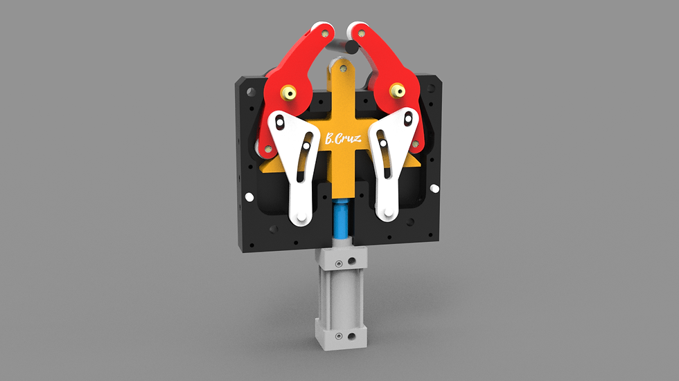
Robotic grippers and clamps | Double-Rocker / toggle | Multiplies gripping or clamping force near the closed position |
How to Model a Four-Bar Linkage in CAD
The workflow is essentially the same whether you're using Fusion 360, SolidWorks, or FreeCAD — only the tool names differ. It's worth dialing in your link lengths and classification in the simulator above first, then transferring those exact numbers into CAD:
Define your link lengths first, as parameters. Before sketching a single body, decide on the ground, crank, coupler, and follower lengths as named parameters (for example, Crank_Length, Coupler_Length, Follower_Length, Ground_Length). Use the simulator to confirm Grashof's condition and the classification you want before modeling anything.
Model each link as a separate body. Keep each link as its own component so you can apply independent joints between them — this also makes it trivial to re-run Grashof's condition later by just changing a parameter.
Pin the ground link. In Fusion 360, right-click the ground component and select Pin (or apply a fixed/rigid joint in SolidWorks) so it doesn't drift when you animate the assembly.
Apply revolute joints at each pin location. Snap to the center of each hole and set the joint type to Revolute for all four connections. This is what actually gives the assembly its one degree of freedom.
Drive the crank and check the motion. Rotate the crank manually (or drive it with a motion study) and confirm the coupler and follower move the way the simulator predicted — full rotation for a Crank-Rocker, oscillation only for a Triple-Rocker.
Trace the coupler curve if needed. If your application depends on a specific path traced by a point on the coupler (common in path-generation problems), compare it against the coupler curve traced live in the simulator, then add a reference point and use CAD's trace or motion-path tool to confirm it before finalizing dimensions.
Designing a Four-Bar Linkage for 3D Printing
A few practical adjustments make the difference between a 3D-printed four-bar linkage that moves freely and one that binds or wears out quickly:
Print pin joints with clearance, not interference. Add roughly 0.2–0.3 mm of diametral clearance between pin and hole for FDM printing — printed holes typically come out slightly undersized due to the way slicers handle small circular features.
Print links flat, on their widest face. This orients layer lines perpendicular to the bending loads the links see in operation, giving better strength at the pin holes where stress concentrates.
Use a separate pin, not a printed-in-place hinge. A short length of filament rod, a printed pin, or a small metal rod/bolt through the joint outlasts a fully printed living hinge for repeated cyclic motion.
Keep joint spacing tight but not zero. A small washer or spacer between overlapping links prevents printed surfaces from rubbing directly against each other, reducing friction and wear at each pivot.
Validate Grashof's condition in the simulator before committing to final dimensions. It's much cheaper to catch a non-rotating crank on screen than to discover it after printing four separate links.
Common Design Mistakes
Skipping the Grashof check. Designing link lengths by eye and discovering afterward that the crank can't fully rotate is the most common — and most avoidable — four-bar mistake. The simulator above makes this a five-second check instead of a hand calculation.
Ignoring the transmission angle. A linkage can satisfy Grashof's condition and still bind badly at one point in its cycle if the transmission angle drops too low there.
Over-tight pin joints. Especially in 3D-printed parts, joints sized with zero clearance seize almost immediately after a few cycles as surfaces wear and swell slightly from friction heat.
Forgetting the coupler curve is not circular. Unlike the crank and follower, the coupler doesn't rotate about a fixed point — assuming its motion is simple or circular leads to interference with nearby components.
Frequently Asked Questions
Is there a free tool to simulate a four-bar linkage online?Yes — the interactive simulator on this page lets you set ground, crank, coupler, and follower lengths and see the resulting motion, Grashof classification, transmission angle, and coupler curve live in your browser, with no download required.
What is the difference between a Crank-Rocker and a Triple-Rocker linkage?In a Crank-Rocker, the shortest link can rotate fully while the opposite link only oscillates. In a Triple-Rocker (non-Grashof), no link connected to the frame can complete a full rotation — every link only swings through a limited arc.
What does Grashof's law actually predict?It predicts whether at least one link in the four-bar chain can rotate a full 360° relative to the others. If the sum of the shortest and longest link lengths is less than or equal to the sum of the two remaining link lengths, the mechanism is Grashof and full rotation is possible somewhere in the chain.
Is a slider-crank mechanism a type of four-bar linkage?Yes. Replacing the follower's ground-side revolute joint with a prismatic (sliding) joint turns a four-bar linkage into a slider-crank mechanism — the same kinematic family used in every reciprocating piston engine.
What transmission angle should I design for?Keeping the minimum transmission angle above roughly 40–45° throughout the cycle is a common practical target for smooth, efficient force transmission, especially under load.
Related Mechanisms
Rack and Pinion Jack Mechanism Explained — another mechanism converting rotary input into controlled linear or mechanical-advantage output.
Tapered Helical Cam Mechanism Explained — a different approach to programmed motion from a single rotary input, using cam geometry instead of a linkage chain.
Geneva Drive Mechanism: How It Works + Animation and Design Explained — for readers exploring other single-degree-of-freedom motion-control mechanisms.
Explore more in 3D Mechanisms and Mechanical Movements.


Comments