Tapered Helical Cam Mechanism Explained: Converting Rotary Motion Into Linear Motion


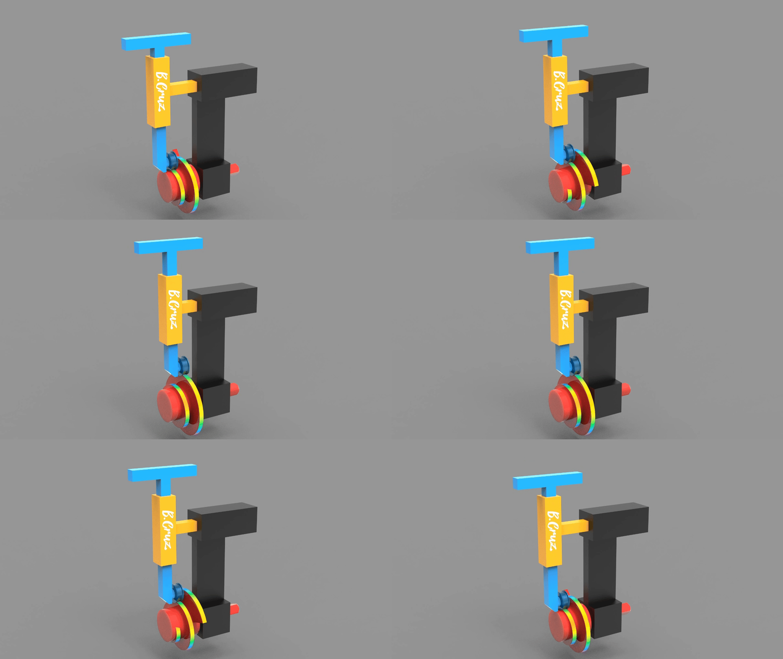
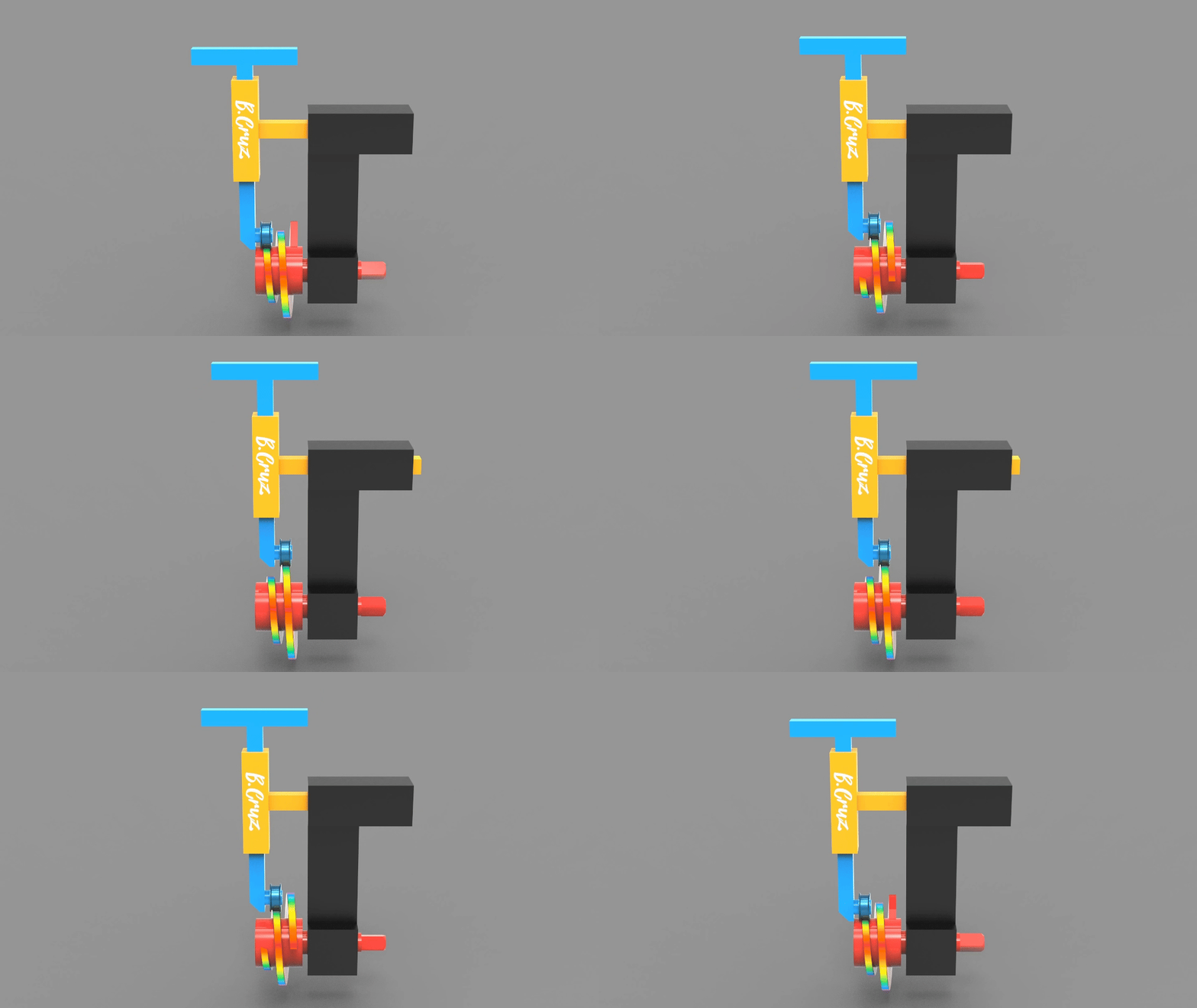
A tapered helical cam mechanism converts reciprocating (back-and-forth) rotary motion into controlled, straight-line linear motion — without a motor pushing directly on the output, and often without a return spring at all. A cam with a helical surface that gradually changes lead angle (the "taper") rotates against a roller follower. As the cam turns, the changing slope of the helix forces the follower to travel up or down along a fixed linear guide. Gravity, rather than a spring, pulls the follower back down and keeps it in constant contact with the cam surface.
It's a deceptively simple idea — one rotating part, one roller, one guide — but the geometry behind it is what makes it precise, repeatable, and mechanically elegant. This article breaks down how it works, how it differs from other cam types, where it's used, and what to consider if you want to model or 3D print one yourself.
What Is a Tapered Helical Cam Mechanism?
A tapered helical cam mechanism is a type of cam and follower system in which the cam's working surface is not a flat plate profile (like a typical disc cam) but a three-dimensional helical surface whose lead — the axial distance the surface advances per revolution — changes progressively along the cam's length. That progressive change is the "taper."
The mechanism has three essential parts:
The tapered helical cam (driver): A rotating body whose surface spirals around its axis with a continuously varying slope. It typically oscillates back and forth (reciprocating rotation) rather than spinning continuously in one direction.
The roller follower: A cylindrical roller that rests directly on the cam's surface, minimizing sliding friction compared to a flat-faced follower.
The linear guide: A fixed track or bushing that constrains the follower bracket to move along a single straight axis, converting the follower's contact point into pure linear output.
As the cam rotates, the follower can't rotate with it — the guide only allows vertical travel — so the mathematical slope of the helix at each angular position is what pushes the follower up. On the return stroke, gravity pulls the follower back down the same profile, so no spring or second powered stroke is needed.
How the Motion Conversion Works, Step by Step
Input: A motor or actuator drives the cam in reciprocating rotation — it turns partway, then reverses, rather than spinning continuously.
Contact: The roller follower sits under continuous preload (its own weight, or added mass) against the helical surface of the cam.
Lift: As the cam rotates, the follower rides along the increasing-lead section of the helix. Because the follower can only move vertically, this rotational contact is translated into upward linear displacement.
Precision from geometry: The relationship between cam rotation angle and follower displacement is entirely defined by the helix's lead angle at each point. A constant lead angle produces constant velocity (linear ramp); a variable — tapered — lead angle lets the designer program acceleration, deceleration, or a dwell directly into the follower's motion.
Return stroke: When the cam reverses direction, the follower descends. Gravity (or, in horizontal installations, a light preload spring) keeps the roller in contact with the surface the entire time, so there's no backlash or "jump" between lift and return.
Because the entire motion profile is cut into the cam's geometry, the follower's velocity and acceleration are fully predictable and repeatable — the same reason cam mechanisms have been the go-to solution for precision timing since long before servo motors existed.
The Geometry Behind the Taper
The core design variable is the lead angle (sometimes called the helix angle), λ, measured between the helical surface and a plane perpendicular to the cam's axis. For a helix with lead L (axial advance per full revolution) and cam radius r:
tan(λ) = L / (2πr)
In a tapered helical cam, r — and therefore λ — changes progressively along the cam's length or across its rotation, instead of staying constant like it would on a simple screw thread. This is what lets the mechanism produce a non-linear lift profile (slow-fast-slow, for example) from a single continuous surface, rather than needing a separate disc cam profile for every segment of motion.
Two practical numbers matter most when sizing a tapered helical cam:
Follower velocity is proportional to the tangent of the local lead angle multiplied by the cam's angular velocity. Steeper sections near the end of the taper move the follower faster for the same rotational speed.
Pressure angle — the angle between the follower's direction of travel and the surface normal at the contact point — should generally be kept below about 30° for roller followers. Beyond that, side loading increases sharply, along with friction and the risk of the follower binding in its guide.
If you're translating this into CAD (Fusion 360 or SolidWorks), the practical approach is to define the desired follower displacement curve first — including any dwell — and derive the helical surface from that curve using a swept or loft feature along a variable-pitch helix, rather than sketching the taper by eye.
Why Gravity Instead of a Spring?
Most cam-follower systems use a spring to keep the follower loaded against the cam, because many cams push the follower away and then rely on the spring to pull it back. A tapered helical cam mechanism can skip the spring entirely when the mechanism is oriented vertically, because:
The follower's own weight (plus any load it carries) supplies constant preload against the cam surface.
There is no sudden unloading event in the motion cycle that would let the follower separate from the cam and "fly off" the profile — the reciprocating rotation and continuous surface contact prevent that.
Removing the spring eliminates spring fatigue, resonance at high cycle rates, and one more component to maintain.
The trade-off is orientation dependency: a gravity-returned design only works with the linear axis reasonably close to vertical, and the design must ensure the follower's weight is enough to overcome friction at every point on the taper, especially the steepest section.
Tapered Helical Cam vs. Other Rotary-to-Linear Mechanisms
Mechanism | Motion type | Return method | Typical use case |
Tapered helical cam | Reciprocating rotary → linear | Gravity or light spring | Programmable lift profiles, textile machinery, wire winding |
Cylindrical (barrel) cam | Continuous rotary → linear (via groove) | Positive-drive groove (no spring needed) | High-speed indexing, packaging machinery |
Plate (disc) cam | Continuous rotary → linear | Spring-loaded follower | Valve trains, low-cost timing mechanisms |
Lead screw / ball screw | Continuous rotary → linear | N/A — positive engagement | High-precision, high-load linear actuation |
Rack and pinion | Continuous rotary → linear | N/A — positive engagement | Long-travel linear motion, steering systems |
The key distinction from a cylindrical (barrel) cam is worth underlining, since the two are often confused: a barrel cam uses a groove cut into a cylinder, and the follower is captured inside that groove, giving positive control in both directions without gravity or a spring. A tapered helical cam instead uses an open surface, relying on the follower staying pressed against it — simpler to manufacture, but dependent on preload (gravity or spring) for the return stroke.
Applications
Tapered helical cam mechanisms show up wherever a machine needs a precisely programmed linear lift synchronized to a rotary input, without the cost or complexity of a servo-driven linear axis:
Textile machinery — controlling the lay of thread or fabric as spindles reciprocate.
Wire winding equipment — traversing a spool axially in a controlled, non-linear pattern to achieve even coil layering.
Custom automation — any station needing a repeatable, programmable lift timed to an oscillating rotary input, such as indexing tables or pick-and-place lift stages.
Scientific and lab instrumentation — low-speed, high-repeatability linear actuation where mechanical simplicity is preferred over electronic control.
Design Considerations for 3D Printing
If you're modeling and printing your own tapered helical cam — as a functional prototype or a demonstration piece — a few practical points make the difference between a mechanism that binds and one that runs smoothly:
Print orientation matters more than usual. The helical surface should be printed so layer lines run roughly parallel to the direction of roller travel, not perpendicular to it — printing across the lead direction creates a stepped, washboard-like surface that the roller will "tick" over instead of rolling smoothly.
Keep the pressure angle conservative. FDM-printed parts have more surface friction and less dimensional precision than machined ones, so staying well under the ~30° pressure angle guideline gives you margin for print tolerance and layer texture.
Use a bearing or low-friction roller, not a printed pin. A printed follower riding directly on a printed cam will wear quickly and add friction that gravity alone may not overcome. A small ball-bearing roller keeps rolling friction low enough for reliable gravity return.
Oversize the linear guide clearance slightly. FDM tolerances typically run a few tenths of a millimeter tight or loose depending on your slicer settings — test-fit the guide bushing before committing to the full assembly.
Post-process the cam surface if precision matters. A light sanding pass on the helical face removes layer stepping and noticeably smooths follower motion, especially at low cam speeds where imperfections are most noticeable.
Common Problems and Troubleshooting
Follower "jumps" or loses contact: Usually means the local pressure angle is too steep for the preload available — either add mass/spring force or redesign the taper to spread the lift over more rotation.
Jerky or uneven motion: Often caused by a discontinuous lead angle (an abrupt change in slope where two curve segments meet). Blend the transition with a smooth spline rather than tangent-matched arcs alone.
Excessive wear at one section of the cam: Typically the steepest part of the taper, where contact force is highest. Consider hardening that zone or lowering the maximum lead angle in the redesign.
Backlash on direction reversal: Check that the follower guide has minimal play; even small clearance is amplified into visible lag at the point where the cam changes direction.
Frequently Asked Questions
What's the difference between a helical cam and a barrel cam? A helical cam has an open surface the follower rides on, requiring gravity or a spring to maintain contact. A barrel (cylindrical) cam uses a closed groove that positively captures the follower, so it doesn't rely on preload for the return stroke.
Can a tapered helical cam run without a spring? Yes, if the mechanism is oriented so gravity keeps the follower loaded against the cam surface throughout the entire motion cycle, including the steepest section of the taper.
What is the maximum recommended pressure angle for this type of cam? Around 30° for roller followers is a common practical limit; beyond that, side loading and friction increase quickly, raising the risk of the follower jumping the profile.
Where is this mechanism used in industry? Textile machinery, wire and coil winding equipment, and custom automation stations that need a repeatable, programmable linear lift driven by an oscillating rotary input.
Want to see this mechanism in motion? Watch the Tapered Helical Cam Mechanism animation on our YouTube channel for a full 3D visualization of the cam, follower, and guide working together.
Related Mechanisms
Geneva Drive Mechanism: How It Works + Animation and Design Explained — another mechanism that converts continuous or reciprocating rotary input into precisely controlled, intermittent motion.
Cone-Roller CVT: A Continuously Variable Transmission Concept — a related example of using tapered/conical geometry to control motion output.
Cardan Joint (Universal Joint) — for readers exploring other rotary motion transmission mechanisms.
Explore more in Mechanical Movements and 3D Mechanisms.


Comments