Oldham Coupling Explained: Connecting Misaligned Shafts With No Backlash Tricks


Two shafts that need to spin together, at exactly the same speed, but whose centerlines don't quite line up — a fraction of a millimeter of offset from a manufacturing tolerance, an assembly that's never perfectly straight, a motor that's slightly off from the load it's driving.
A rigid coupling would bind or wear rapidly under that kind of misalignment. This mechanism solves it with three simple parts and no bearings, no gears, and no flexible material to fatigue over time.
It's called an Oldham coupling, and it's been solving this exact problem since 1821.
A Little History
The mechanism is named after John Oldham, an Irish engineer who invented it to solve a specific problem on a paddle steamer design, where the paddle wheel shafts needed to be connected despite not sitting perfectly in line.
Two centuries later, the same three-piece principle is still the standard solution wherever a compact, backlash-tolerant connection between two slightly offset parallel shafts is needed — from servo drives and CNC retrofits to consumer devices like printer drum couplings.
What Is an Oldham Coupling?
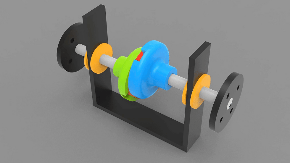
An Oldham coupling connects two parallel shafts using three parts:
The driving hub, keyed or clamped to the input shaft, with a straight slot cut across its face.
The driven hub, keyed or clamped to the output shaft, with an identical slot cut across its face — but oriented 90° from the driving hub's slot.
The floating center disc, sandwiched between the two hubs, with a tongue on each face — one tongue per side, and the two tongues oriented at 90° to each other, matching the perpendicular slots on the two hubs.
Because the center disc's two tongues are perpendicular to each other, each tongue can slide freely along its matching hub's slot in one direction while staying rigidly engaged in the other direction.
That combination — free sliding on one axis, rigid engagement on the perpendicular axis, on both sides of the floating disc — is what lets the whole assembly transmit rotation while quietly absorbing a small parallel offset between the two shaft centerlines.

Download the CAD File
Grab the CAD files (it’s free)
How It Works
Rotation begins. The driving hub, fixed to the input shaft, starts to rotate.
Engagement through the tongue. The driving hub's slot pushes against the center disc's matching tongue, transmitting torque into the disc.
The disc transmits, and slides. The disc passes that same rotational motion through to the driven hub via its second tongue — engaged in the driven hub's slot, which is oriented 90° from the first. Where the shaft centerlines aren't perfectly aligned, the disc continuously shifts position slightly within both slots as it rotates, sliding back and forth along each slot's axis to compensate for the offset.
Constant angular velocity. Despite that continuous small sliding motion, the coupling is designed so the output shaft's rotational speed exactly matches the input shaft's — the offset is absorbed entirely as lateral sliding of the disc, not as any variation in rotational speed.
Cycle repeats. With each revolution, the disc's position relative to each hub traces the same repeating pattern, continuously accommodating the same fixed misalignment without needing any adjustment.
Why It's Called the "Third Inversion" of a Kinematic Chain
If you've read our four-bar linkage guide (https://www.3dmechanism.com/post/four-bar-linkage-mechanism-explained), this connects directly: an Oldham coupling is classified in mechanism theory as the third inversion of a double slider-crank chain — the same family of four-link kinematic chains, just with two of the revolute (pin) joints replaced by sliding (prismatic) joints instead of one, as in a standard slider-crank.
Which link is held fixed, and which joints are sliding versus rotating, determines whether a given double-slider-crank chain behaves as an Oldham coupling, an elliptical trammel, or another mechanism in the same family — the Oldham coupling is simply the specific inversion where the "fixed" link is effectively replaced by the requirement that both hubs rotate at the same speed.
What It Corrects For — and What It Doesn't
An Oldham coupling is specifically built to handle parallel (lateral) shaft misalignment — the two shaft centerlines are offset but still pointing in the same direction.
It is generally not the right choice for significant angular misalignment, where the two shaft centerlines meet at an angle rather than running parallel; that's a job better suited to a universal (Cardan) joint or a flexible bellows coupling.
Most practical designs do tolerate a small amount of incidental angular misalignment, but it isn't the mechanism's intended function, and pushing it past a small margin concentrates load at the tongue ends rather than across the full sliding face.
Oldham Coupling vs. Other Misalignment Solutions
Oldham Coupling | Flexible (Bellows/Beam) Coupling | Universal (Cardan) Joint
Handles parallel offset: Yes (primary) | Yes (smaller range) | Poorly
Handles angular misalignment: Limited | Yes (moderate) | Yes (primary)
Backlash: Very low with proper fit | Very low | Can be higher at large angles
Speed ratio: Constant 1:1 | Constant 1:1 | Non-constant at an angle unless double-joint
Serviceability: Replaceable center disc | Typically non-serviceable flexure | Bearings/rollers, more complex
The Oldham coupling's biggest practical advantage over a flexible coupling is that the center disc is a simple, inexpensive, replaceable wear item — when it eventually wears from repeated sliding, you swap the disc rather than the entire coupling.
Real-World Applications
Servo motor and encoder connections — compensating for the small misalignment that's nearly unavoidable when coupling a motor shaft to a separately-mounted encoder or leadscrew.
CNC machine retrofits — connecting a new motor to an existing leadscrew or spindle where perfect shaft alignment isn't practical to achieve.
Printer and copier drum drives — coupling a drive shaft to a removable, user-replaceable drum or cartridge, where exact alignment can't be guaranteed every time the cartridge is swapped.
Pumps and light industrial machinery — connecting motor to pump shafts where mounting tolerances introduce some unavoidable offset.
Textile machinery — the coupling's original application area, dating back to its 1821 invention.
Designing an Oldham Coupling in CAD
Model the two perpendicular slots and tongues from a shared reference plane, not sketched independently on each part — the 90° relationship between the two axes is the entire mechanism, and even a small angular error between them shows up as binding rather than smooth sliding.
Size the slot width to the tongue thickness with a genuine sliding fit, not a snug one — this joint needs to slide freely under load, so treat it as a linear bearing surface, not a keyed connection.
Model the disc's maximum offset capability explicitly, based on your slot length and tongue width, so you know the coupling's actual misalignment tolerance for your specific dimensions rather than assuming a generic "small offset is fine" rule.
Run a motion study through a full rotation at your design's maximum intended offset, not just at perfect alignment — this is what actually reveals whether a tongue runs out of slot length or starts to bind at any point in the cycle.
Designing for 3D Printing
Choose a low-friction material for the center disc specifically, even if the hubs are printed in a standard structural filament — the disc is the part doing all the sliding, and a lower-friction, wear-resistant plastic there noticeably outperforms the same material used throughout.
Print the disc's tongues oriented so layer lines run along the sliding direction, not across it — sliding across raised layer lines increases friction and accelerates wear at exactly the contact surface that matters most.
Give the slot-to-tongue fit real clearance, verified with a test print, rather than trusting the nominal CAD dimension — FDM tolerances are usually tight enough that a "perfect fit" in the model prints as an interference fit in practice.
Consider a thin low-friction liner or bushing insert in the slots if the coupling will run continuously rather than intermittently — this is a simple upgrade that meaningfully extends the wear life of a printed design.
Common Problems and Troubleshooting
Excessive backlash or play: Usually oversized slot-to-tongue clearance — this is the main tradeoff in Oldham coupling design, since the fit needs to be loose enough to slide freely but tight enough to avoid noticeable lash.
Premature wear or cracking at the tongue root: Often a sign the coupling is being run beyond its rated offset, concentrating load at the tongue's base rather than distributing it across the sliding contact.
Coupling binds instead of sliding smoothly: Check that the two slots are genuinely perpendicular and coplanar with each other — even a small angular error between the two hub slot orientations turns free sliding into intermittent binding.
Frequently Asked Questions
What kind of shaft misalignment does an Oldham coupling correct for?
Parallel (lateral) misalignment, where the two shaft centerlines are offset but still pointing in the same direction — it's generally not the right choice for significant angular misalignment, which is better handled by a universal joint or a flexible coupling.
Why does the center disc have two tongues at 90° instead of one?
Each tongue slides freely along its matching hub's slot in one direction while staying rigidly engaged in the perpendicular direction. With two tongues oriented 90° apart, the disc can absorb offset in any direction within its plane while still transmitting rotation at a constant 1:1 speed ratio.
Does an Oldham coupling introduce any speed variation between the input and output shafts?
No — properly designed, the output shaft's speed exactly matches the input shaft's throughout the rotation; the misalignment is absorbed entirely as sliding motion of the center disc, not as any variation in angular velocity.
Why replace just the center disc instead of the whole coupling?
Because the disc is the only part doing sliding, wear-prone work — the two hubs experience essentially no relative sliding wear, so a worn coupling can typically be restored to like-new performance with just a disc replacement rather than a full assembly swap.
Related Mechanisms
Four-Bar Linkage Explained (with Interactive Simulator): https://www.3dmechanism.com/post/four-bar-linkage-mechanism-explained
Explore more in 3D Mechanisms: https://www.3dmechanism.com/3dmechanism
Mechanical Movements: https://www.3dmechanism.com/3dcadsketches/categories/2d-sketch


Comments